-
乐动在线官网-(中国)官方网站
-
公路检测
-
地球科学
-
室内岩土
-
无损检测
-
原位测试
-
材料检测
-
传感数采
-
-
实验方法
-
道路桥梁机场轨道工程
-
建筑及基础设施工程
-
科研及人才培养
-
海洋工程
-
资源勘查与研究
-
航空与机械工业
-
- 行业应用
- 解决方案
-
技术与服务
- 乐动在线官网-(中国)官方网站
-
社区
- 购买
- En
在深海风机与油气平台服役期间,粉质砂海床与钢管桩之间的界面在循环荷载作用下发生毫秒级剪切响应。浙江大学海南研究院科研团队利用GDS环剪/界面剪切仪,系统开展50次等幅循环剪切试验,系统量化该界面的强度与变形演化规律。2025年7月7日,团队在《Acta Geotechnica》期刊发表了题为《Mechanical behavior at silty sand-steel interface undergoing cyclic shearing》(粉砂–钢界面在循环剪切作用下的力学行为)的学术论文,总结了该科研项目的进展。
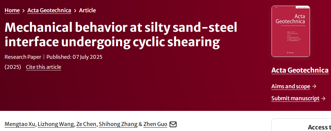
https://doi.org/10.1007/s11440-025-02694-9
*论文版权归原作者和出版方所有,本文仅为学习交流。
以下是对这项成果的简要介绍:
考虑到海床土与结构地基在材料特性上的显著差异,准确描述土-结构接触面的力学行为至关重要。本研究进行了多次循环界面剪切试验,以研究多边界条件下粉砂-钢界面的强度和变形特性。对界面的抗剪强度、体积变形、动摩擦角和液化趋势进行了量化。细粒含量的增
加使土骨架由砂-砂接触过渡到细-砂、细-细接触,剪切行为由剪胀剪缩交替转变为以剪缩为主。随着循环次数的增加,由于界面恢复能力的退化,连续循环中累积位移和循环位移分量的差异减小,同时伴随着相变应力的降低。在高应力条件下,土颗粒间更紧密的相互作用增强了抗液化能力,而循环幅值的增加使界面剪胀得到更充分的表达,这都有助于延迟液化的发生。通过引入包含细粒含量、初始法向应力和循环幅值影响的特征循环,建立了表征界面快速液化破坏的界面液化公式。
团队以南海某风电场原状粉质砂为对象,在三种边界条件(CNL常法向力、CNS常法向刚度、CV常体积)下,用GDS环剪/界面剪切仪完成了近百组循环剪切试验。变量覆盖细颗粒含量FC=0–100%、初始法向应力σn0=50–400 kPa、循环幅值δ=0.5–4 mm,最高连续50个循环。
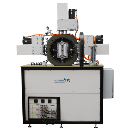
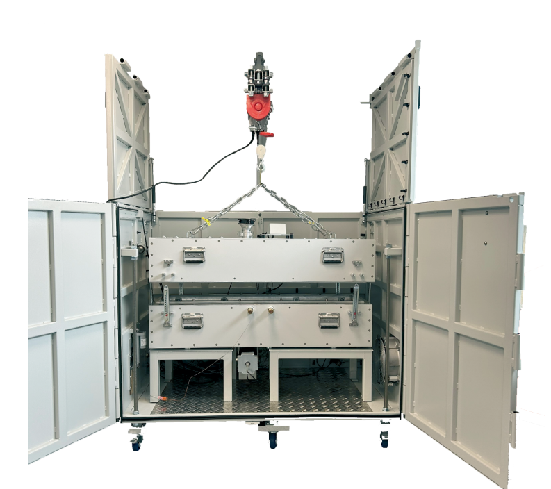
GDS环剪仪
基于循环界面剪切试验,研究揭示了粉质砂-钢界面的力学行为规律:
1
细颗粒含量的核心作用
随细颗粒含量增加,土体骨架从砂-砂接触转向细颗粒主导接触,剪切行为由交替剪胀-剪缩转变为持续剪缩主导。在CNL条件下,高细颗粒含量需更大剪切位移达到峰值强度,刚度降低;CNS条件下,细颗粒加速剪切强度退化(50次循环后,FC=100%时退化达99.5%);CV条件下则触发法向应力骤降与孔压积聚。
2
边界条件与应力影响
(1)法向应力增大强化颗粒破碎与剪缩,但增强抗液化能力;
(2)大循环幅值促使剪切初期剪缩、后期剪胀(颗粒破碎导致剪缩复现),同时充分激发剪胀特性以延缓液化;
(3)液化临界点:细颗粒含量≥30%时,首循环即发生液化,法向应力与幅值影响失效。
3
法向位移演化特征
位移分为累计分量(CUV)与循环分量(CCV)。循环次数增加导致二者差异减小,表明界面恢复能力衰退及相变应力降低。CCV生成慢于回复(达峰值位移>回复位移),且受细颗粒含量增高、法向应力增大抑制而减弱。CCV饱和后增速急剧下降。
4
液化判别方法
针对界面液化速度快于土体的特性,提出基于特征循环数的判别公式,关键参数包括细颗粒含量、初始法向应力及循环幅值。
*图表为论文截图,版权归论文原作者和出版方所有,本文仅为学术交流。
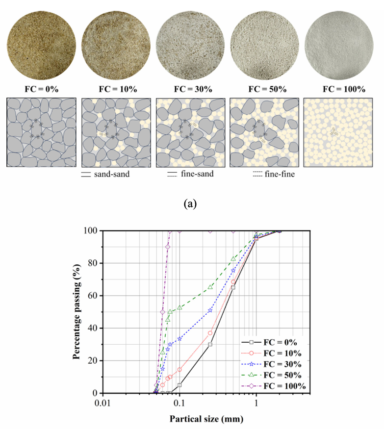
Fig. 1 a Sand sample and schematic diagram of force chain; b Particle size distribution
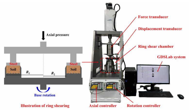
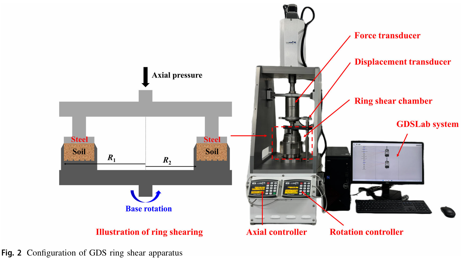
Fig. 2 Configuration of GDS ring shear apparatus
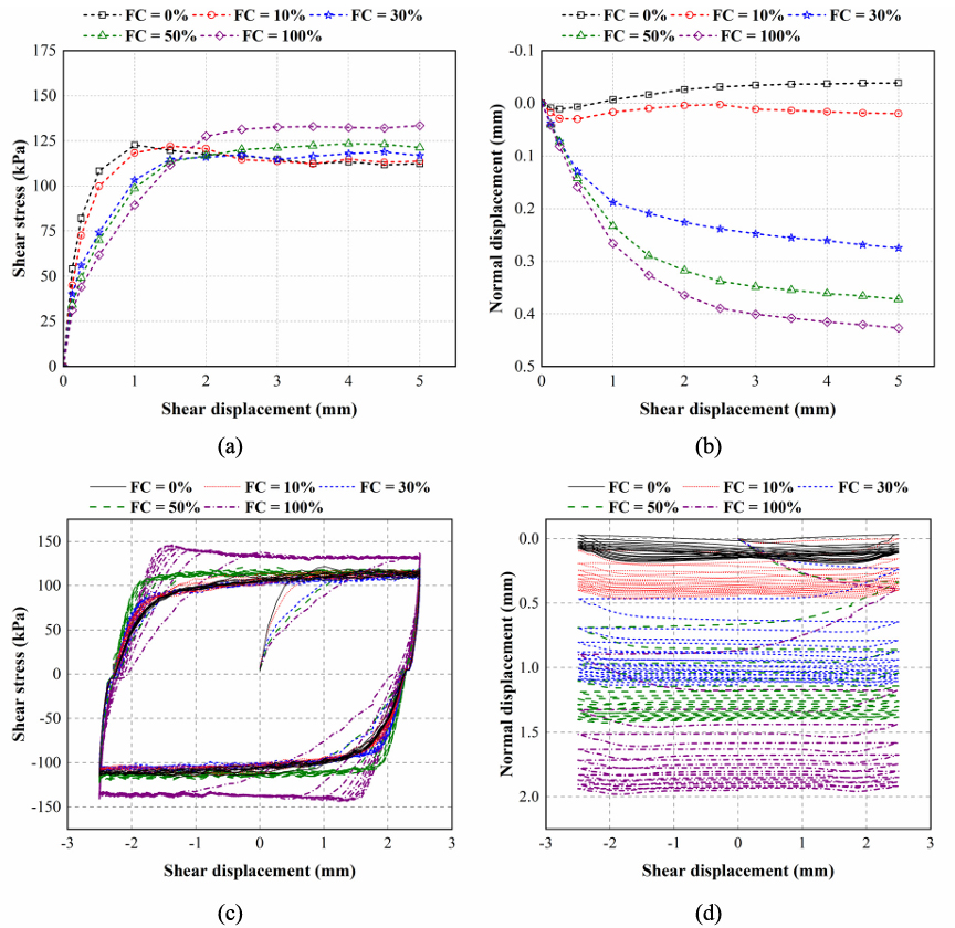
Fig. 3 a, b Monotonic interface shear results under CNL: Evolution of a shear stress, and b normal displacement versus shear displacement; c, d Cyclic interface shear results of Test C1 under CNL: Evolution of c shear stress, and d normal displacement versus shear displacement
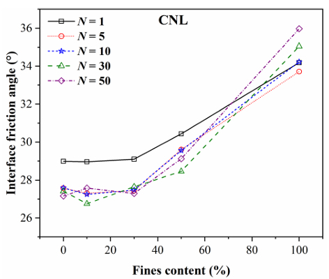
Fig. 4 Interface friction angle for soil samples with different fines content after N cycles
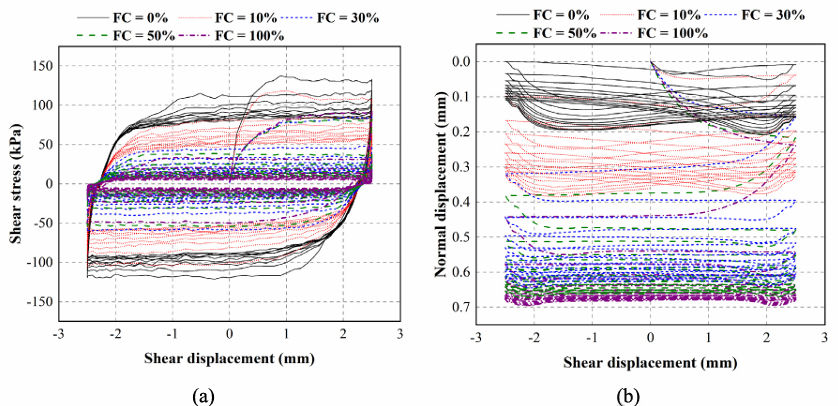
Fig. 5 Cyclic interface shear results of Test C2 under CNS: Evolution of a shear stress, and b normal displacement versus shear displacement
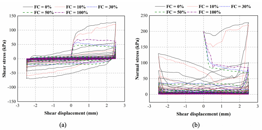
Fig. 6 Cyclic interface shear results of Test C3 under CV: Evolution of a shear stress, and b normal stress versus shear displacement
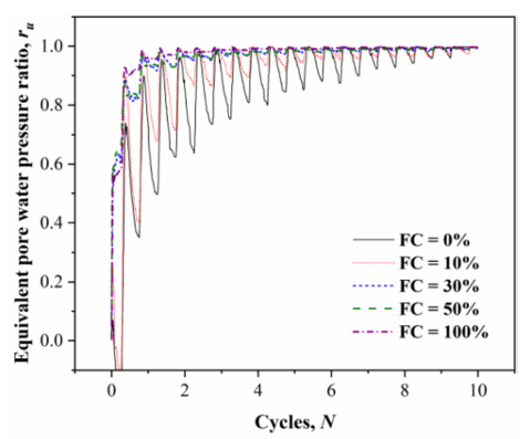
Fig. 7 Liquefaction trend at the interface in Test C3 under CV
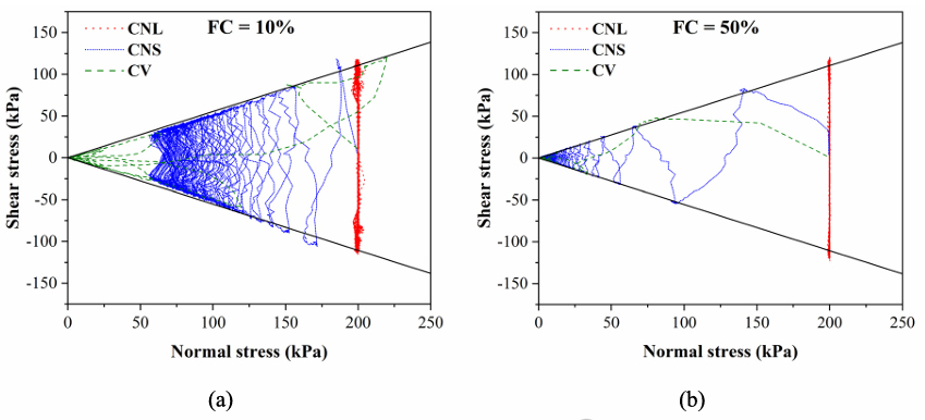
Fig. 8 Relationship between shear stress and normal stress under different normal boundaries: a FC = 10%; b FC = 50%
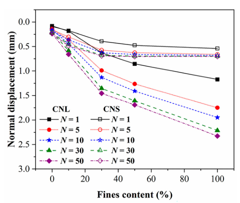
Fig. 9 Change in normal displacement under CNL and CNS boundary conditions
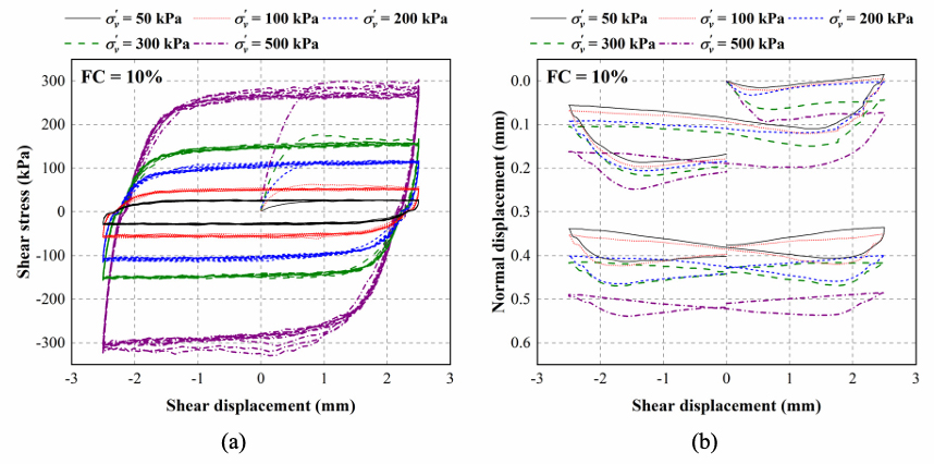
Fig. 10 Cyclic interface shear results of Test C6 under CNL with varying initial normal stress: Evolution of a shear stress, and b normal displacement versus shear displacement
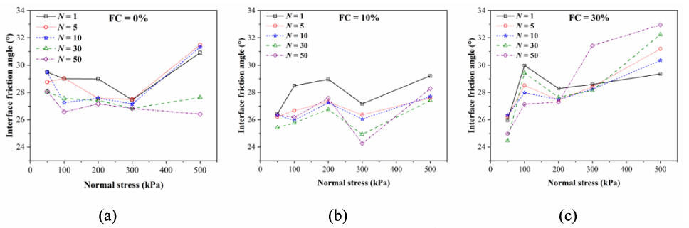
Fig. 11 Mobilized interface friction angle after N cycles under varying initial normal stress: a FC = 0%; b FC = 10%; c FC = 30%
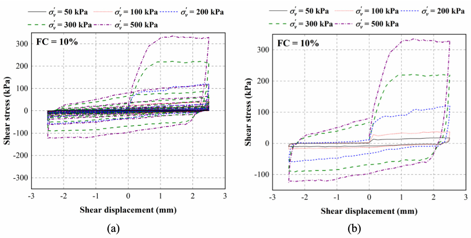
Fig. 12 Cyclic interface shear results of Test C7 under CV with varying initial normal stress: a Evolution of shear stress versus shear displacement; b The initial cycle in Fig. 12a
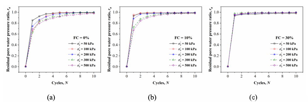
Fig. 13 Liquefaction trend at the interface under varying initial normal stress: a FC = 0%; b FC = 10%; c FC = 30%
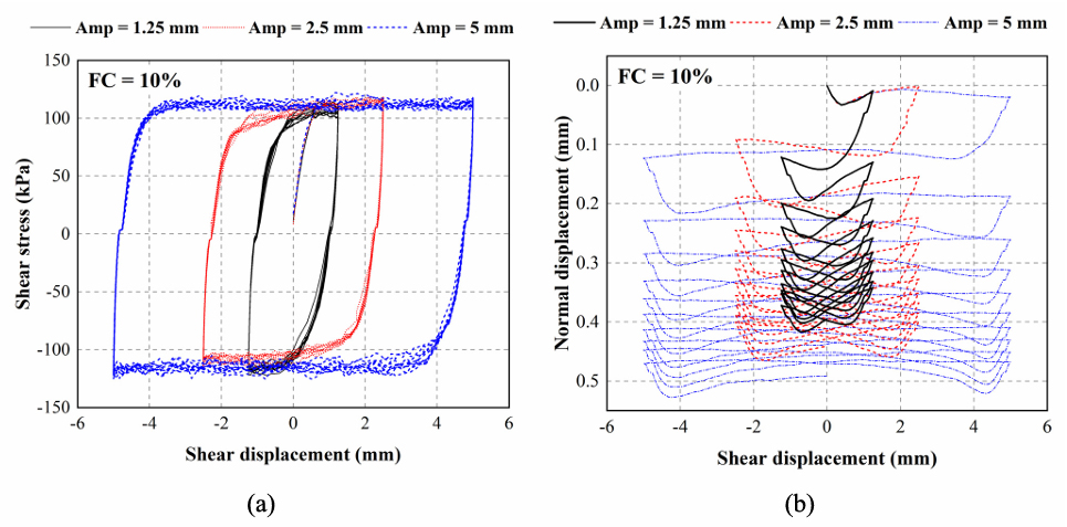
Fig. 14 Cyclic interface shear results of Test C12 under CNL with different cyclic amplitude: Evolution of a shear stress, and b normal displacement versus shear displacement
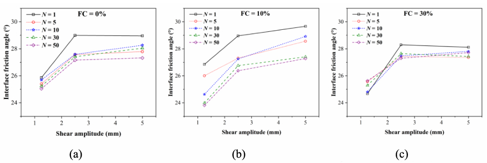
Fig. 15 Mobilized interface friction angle after N cycles with different cyclic amplitude: a FC = 0%; b FC = 10%; c FC = 30%
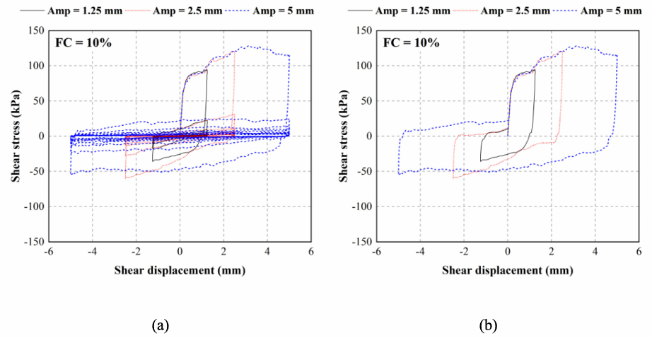
Fig. 16 Cyclic interface shear results of Test C13 under CV with different cyclic amplitude: a Evolution of shear stress versus shear displacement; b The initial cycle in Fig. 16a
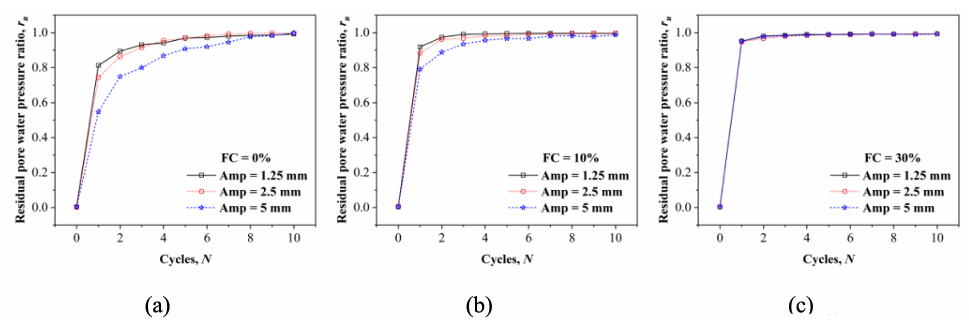
Fig. 17 Liquefaction trend at the interface with different cyclic amplitude: a FC = 0%; b FC = 10%; c FC = 30%
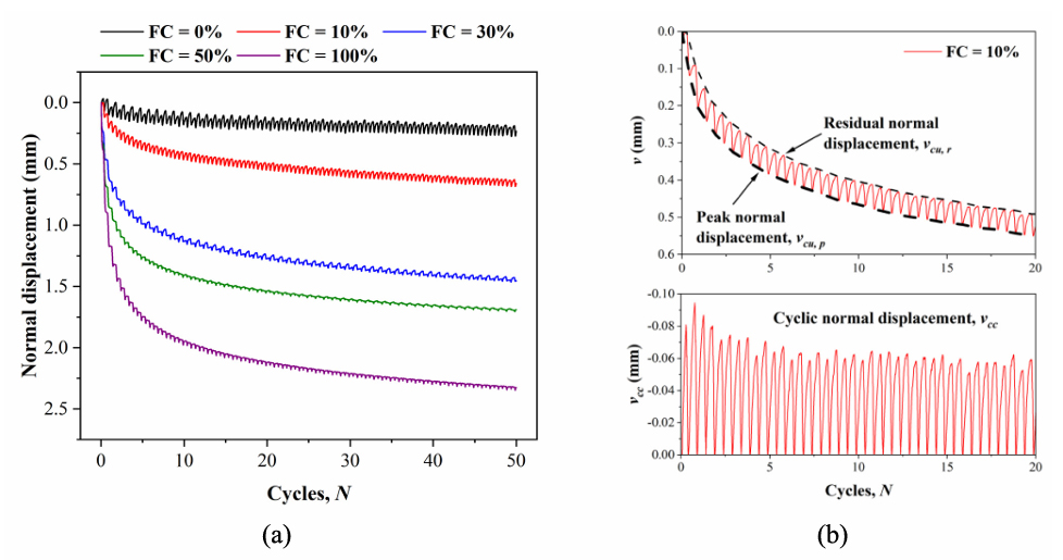
Fig. 18 Evolution of normal displacement versus number of cycles: a Total normal displacement; b Cumulative and cyclic normal displacement
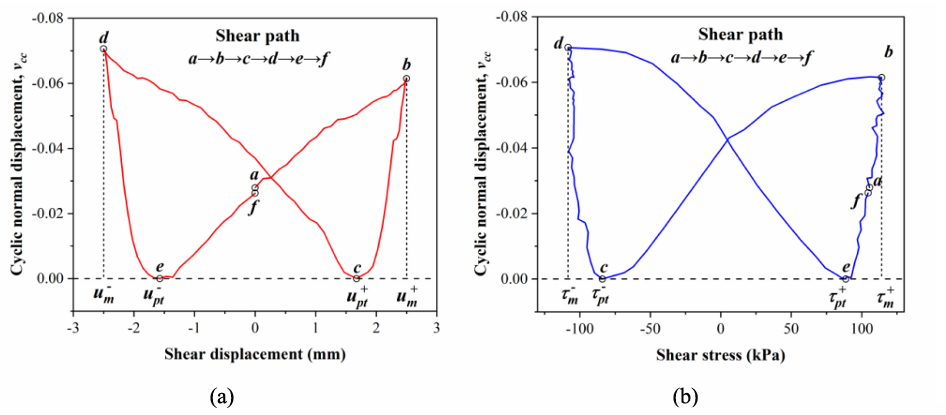
Fig. 19 Cyclic normal displacement relative to a Shear displacement; b Shear stress
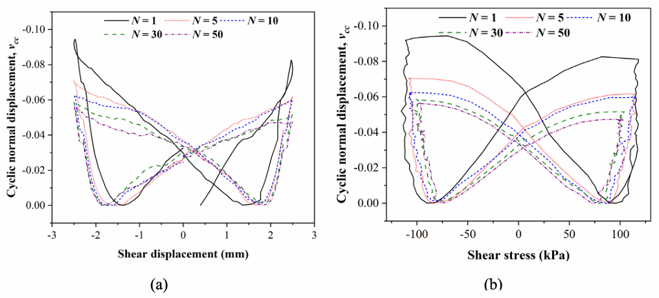
Fig. 20 Evolution of cyclic normal displacement with different number of cycles, relative to a Shear displacement; b Shear stress
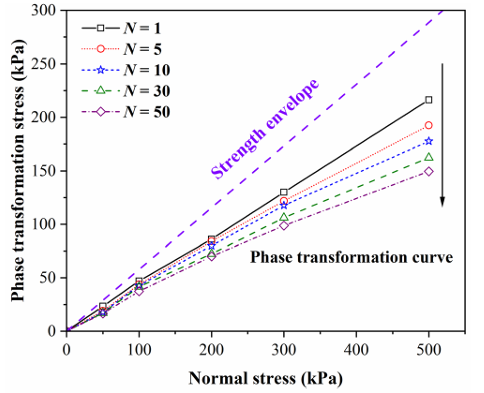
Fig. 21 Change in phase transformation stress under different initial normal stresses
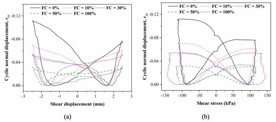
Fig. 22 Evolution of cyclic normal displacement with different fines contents, relative to a Shear displacement; b Shear stress
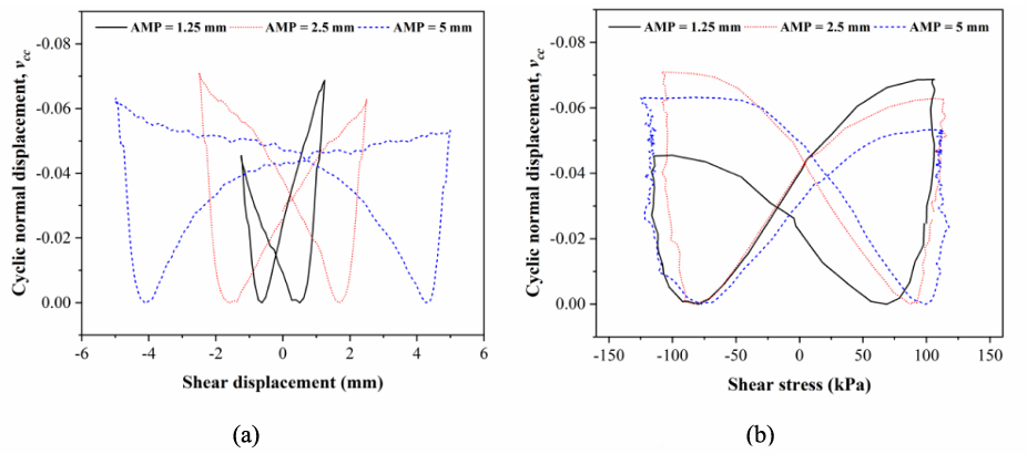
Fig. 23 Evolution of cyclic normal displacement with different cyclic amplitude, relative to a Shear displacement; b Shear stress
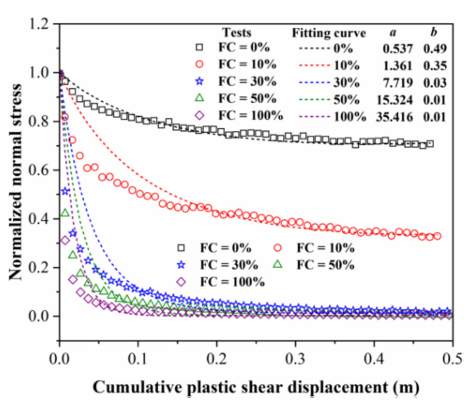
Fig. 24 Degradation of interface normal stress under CNS condition
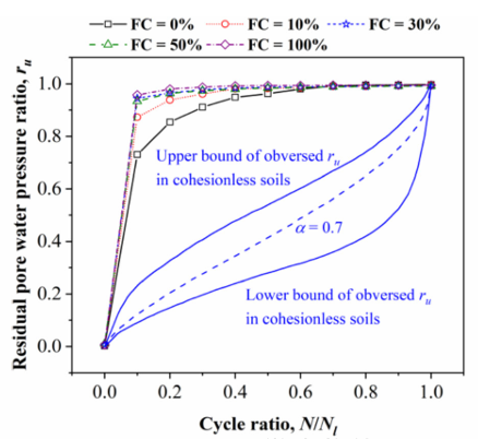
Fig. 25 Evolution of residual pore water pressure at the interface
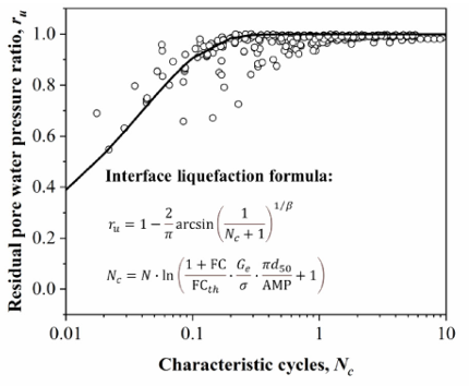
Fig. 26 Prediction of residual pore water pressure ratio utilizing the interface liquefaction formula
GDS环剪/界面剪切仪GDSRSA
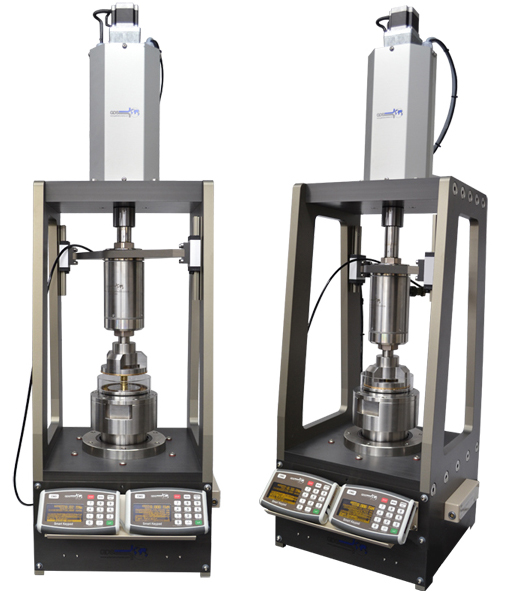
GDSRSA是一个现代化的、紧凑的、桌面化的环剪系统,允许完全自动化的试验。该GDSRSA允许进行扭转环剪试验。在排水条件下,通过步进电机连续施加旋转剪切作用力直到获得恒定的残余剪切应力。在试验过程中,试样的横截面区域的剪切面不变。GDS的环状剪切仪通过GDS力作动器施加固结应力,通过计算机(用USB连接)来进行控制和数据采集,外置的荷载传感器直接测量施加到样品上的轴向和剪切应力。
通过增加选配件可实现界面剪试验。
系统特点及优势:
主要特点 | 优点 |
尺寸小、重量轻 | 该台式系统占地面积小(为51 x32cm)、重量轻(30kg),很容易搬动。 |
完全内置的系统 | GDS环剪仪不需要额外的数据采集仪、额外笨重的外置压力表和荷重环,所有要求的连接件和设备都全部直接安装于设备中 |
外置局部LVDT传感器 | 有闭环的外置LVDT记录轴向位移,不包含于系统中,这样就能允许更准确的测试 |
主动高度控制允许进行恒定体积环剪试验 | 液化抗剪强度的测定,该试验要求显著的剪切应变和高度控制(恒定体积),因此在GDSRSA中是理想的 |
可互换的底座和顶帽 | 允许一台机器来测试各种样品尺寸(如果需要的话)。底座和顶帽使用锁定夹在框架内固定 |
轴向位移通过DIGIRFM连接 | 使用位移或应变目标控制时有闭环位移增减反馈 |
试样下部引流 | 允许试验过程中试样排水 |
随机透水板类型 | 减少试样皱裂 |
2根USB电缆用于计算机控制 | 允许用户友好方式连接到任一台现代的计算机 |
技术参数:
试样尺寸 | 100mm外径×70mm内径(其他尺寸可根据要求提供) |
分辨率 | 荷载1N,位移1微米,角位移:0.01度,扭距0.01Nm |
最大速度 | (旋转)2.25°/ S (135°/分钟) |
最大扭矩 | 200Nm |
最大轴向荷载 | 5kN |
最大应力 | 轴向:1200kPa;剪切:1100kPa |
外置LVDT量程 | +/-5mm |
外形尺寸(WxDxH)&重量 | 51×32×116cm- 30kg |
标准 | ASTM-D7608-10, ASTM-D6467-13,BS1377,1990年第7部分 |
供电要求 | 100-240V 50/60Hz 1.5A 单相电 |